Sewage will inevitably be mixed with mud and sand in the process of migration, flow and collection. If the sand in sewage is not pre-settled and separated, it will affect the operation of subsequent treatment equipment. The most important is the abrasion pump, blocking the pipe network, interfering with or even destroying the biochemical treatment process.
I. Applicable Objects
Sand sink removes coarse particles such as mud and sand from sewage. It is mainly used to remove sand particles with particle size greater than 0.2mm and density greater than 2.65t/cubic meter in sewage to protect pipelines, valves and other facilities from wear and clogging.
II. The Role of Sand Settlement Tank in Sewage Treatment
The pool accounts for a small proportion of investment and land occupation in sewage treatment plants, but its role can not be ignored. If the sedimentation tank is cancelled, a large number of sand particles will enter the subsequent treatment units, which will bring many hidden dangers to the normal operation of the sewage plant.
1. Sand entering the primary settling tank will accelerate the wear of the sludge scraper and shorten its service life.
2. The deposition of sand particles in sludge discharge pipeline can easily lead to blockage of pipeline, which will aggravate impeller wear after entering sludge pump.
3. For the treatment process without primary sedimentation tank (such as oxidation ditch, CASS, etc.) or the process in which the initial sedimentation tank runs beyond the initial sedimentation tank because of the low water inflow load in actual operation, a large number of sand particles will directly enter the biochemical tank to deposit, resulting in the reduction of the effective volume of the biochemical tank, and will also have adverse effects on the aerator.
4. Sand particles entering sludge digestion tank will reduce the effective volume and shorten the cleaning cycle.
5. The increase of sand content in sludge will greatly affect the operation of sludge dewatering equipment. Sand entering into belt dewatering will aggravate the wear of filter cloth, shorten the replacement cycle, at the same time, it will affect the flocculation effect and reduce the cake formation rate of sludge. In recent years, horizontal screw centrifuges have been widely used in urban sewage treatment plants. Due to the high-speed centrifugal separation of the equipment, the wear of the rotating cylinder and screw will be greatly increased.
III. General Regulations for Sand Settlement Tanks
1. Municipal sewage treatment plants should generally set up sand sinks.
2. Sand sink is designed to remove sand particles with relative density of 2.65 and particle size of 0.2 mm.
3. Sewage flow rate should be considered by stages; when sewage is left in the plant, it should be calculated according to the maximum design flow rate of each period; when sewage pump is lifted into the site, it should be calculated according to the maximum combined flow rate of each working pump; in the combined system, it should be calculated according to the design flow rate of rainfall.
4. The number of sand sinks or sub-lattices shall not be less than 2 (lattices) and shall be designed in parallel.
5. The sediment amount of municipal sewage is calculated as (15-30 m3)/(10 ^ 6 m3). Its water content is 60%, its bulk density is 1500 kg/m3, and the combined sewage is determined according to the actual situation.
6. The bucket volume is calculated according to the amount of sand deposited in 2 days. The angle between bucket wall and horizontal plane is not less than 55 degrees.
7. In general, mechanical sand removal and sand storage tanks should be adopted. The diameter of sand discharge pipe should not be less than 200 mm.8. When gravity is used for sand removal, the sedimentation tank and the storage tank should be as close as possible.
8. When gravity is used for sand removal, the sedimentation tank and the storage tank should be as close as possible.
IV. Types of settling basins
According to the different direction of flow in the pond, it can be divided into advection type, aeration type and cyclone type.
1. Advection Sand Settlement Tank

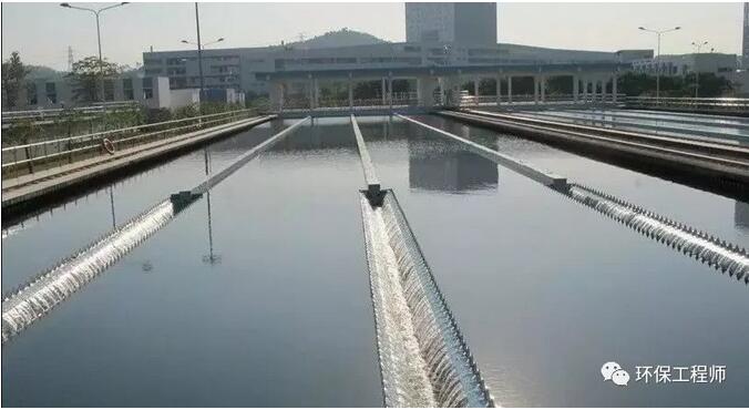
The horizontal sand settling tank is a common type, in which sewage flows horizontally. The advection sand sink consists of an inflow channel, an outflow channel, a gate, a flow part and a sand bucket. It has many advantages, such as good effect of intercepting inorganic particles, stable operation, simple structure and convenient sand drainage.
Design parameters:
1) The maximum velocity is 0.3m/s and the minimum velocity is 0.15m/s.
2) The residence time is not less than 30 seconds at the maximum flow rate, usually 30-60/s.
3) Effective water depth should not be less than 1.2m, generally 0.25-1m, and the width of each cell should not be less than 0.6m.
4) Energy and rectification measures should be abolished at the intake head.
5) Pool bottom slope is generally 0.01-0.02. When setting sand removal equipment, the shape of pool bottom can be considered according to the requirements of equipment.
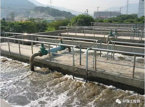
2. Aerated Sand Settlement Tank

The typical feature of the aerated sand sink is that the aeration device is installed in the tank, which can have the following effects on the sewage in the tank:
a) Sand grains flow forward in a spiral shape in a sand sink;
b) to keep organic particles in suspension;
c) It can remove the organic pollutants adhering to the sand particles by friction between the sand grains, which is conducive to obtaining cleaner sand grains and other inorganic particles.;
d) Aeration also removes grease and synthesizes detergents.
Design parameters:
1)The swirl velocity should be kept from 0.25 to 0.3 m/s.
2)Horizontal velocity is 0.06-0.12m/s.
3)Residence time at maximum flow rate is 1-3 minutes.
4)The effective water depth is 2-3 m, and the width-depth ratio is generally l-2.
5)The ratio of length to width can reach 5. When the length of the pool is much larger than the width of the pool, the transverse baffle should be considered.
6)The aeration of 1 m3 sewage is 0.2 m3 air.
7) The air diffusion device is located on one side of the pool, about 0.6-0.9 m away from the bottom of the pool. The gas supply pipe should be equipped with a gate to regulate the gas flow.
8)The shape of the pool should not produce deviation or dead angle as far as possible. Longitudinal baffles can be installed near the sand collecting trough.
9)Short circuit should be prevented in the layout of the inlet and outlet of the pool. The direction of water inflow should be consistent with the direction of swirl in the pool, and the direction of water outflow should be vertical to the direction of water inflow, and baffles should be considered.
10)Defoaming devices should be considered in the tank.
3. Swirling Sand Settler
At present, the swirling sand sinks widely used in the world are mainly of two types: Zhong's and Bi's. From the domestic application situation, the majority of Zhongshichi pool and its variants originated from Europe.
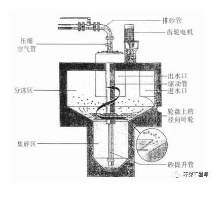
Bell-type sandy ground uses mechanical force to control the flow pattern and velocity and accelerate the precipitation of sand grains. Sand settling device for carrying organic matter away with water flow.

Sand sink is composed of flow inlet, flow outlet, sand sinking area, sand bucket, sand riser, sand discharge pipe, motor and gearbox. Sewage flows into the sediment area along the tangential direction from the inlet, and rotates the rotating disc and slope blade by the motor and transmission device. Under the action of centrifugal force, the sand particles with higher density in the sewage are thrown to the wall of the pond and dropped into the sand bucket, while the organic matter is left in the sewage. By adjusting the rotational speed, the best sand settling effect can be achieved. Sand settling is cleaned by compressed air through sand lifting pipe and sand draining pipe, and the cleaning water is returned to the sand settling area.
Design parameters:
1)The hydraulic surface load should be controlled at about 200 m3/(m2 * h).
2)Hydraulic residence time should be controlled in 20-30 s.
3)Flow velocity of intake channel: 1) when the maximum flow rate is 40%-80%, it is controlled at 0.6-0.9m/s; 2) when the minimum flow rate is greater than 0.15m/s; 3) when the maximum flow rate is not greater than 1.2m/s.
4) The length of the straight section of the intake channel is 7 times the width and should not be less than 4.5m.
5)The width of the outlet channel is twice as wide as that of the intake channel.
6)The angle between the outlet channel and the intake channel is more than 270 degrees.
